Before any firmware could be written, three separate questions needed answers: where physically on the board is the radio MCU’s debug interface, what security state is the silicon actually in, and how does the router’s main SoC talk to it in normal operation. Each stage deliberately reduced risk before the next, moving from photographs, to unpowered continuity measurements, to read-only silicon interrogation, and only then to writes.
Locating the radio and avoiding the wrong test points
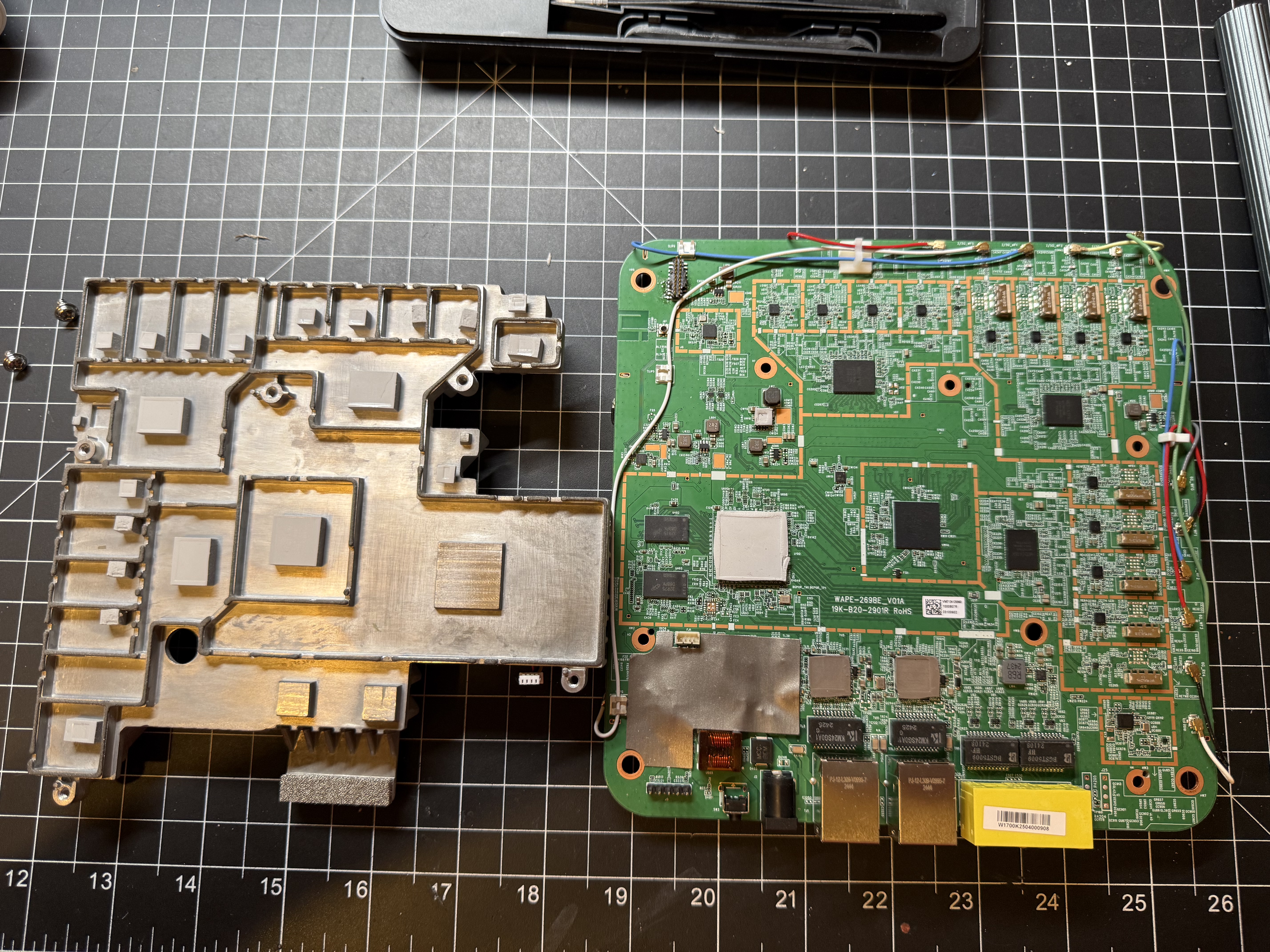
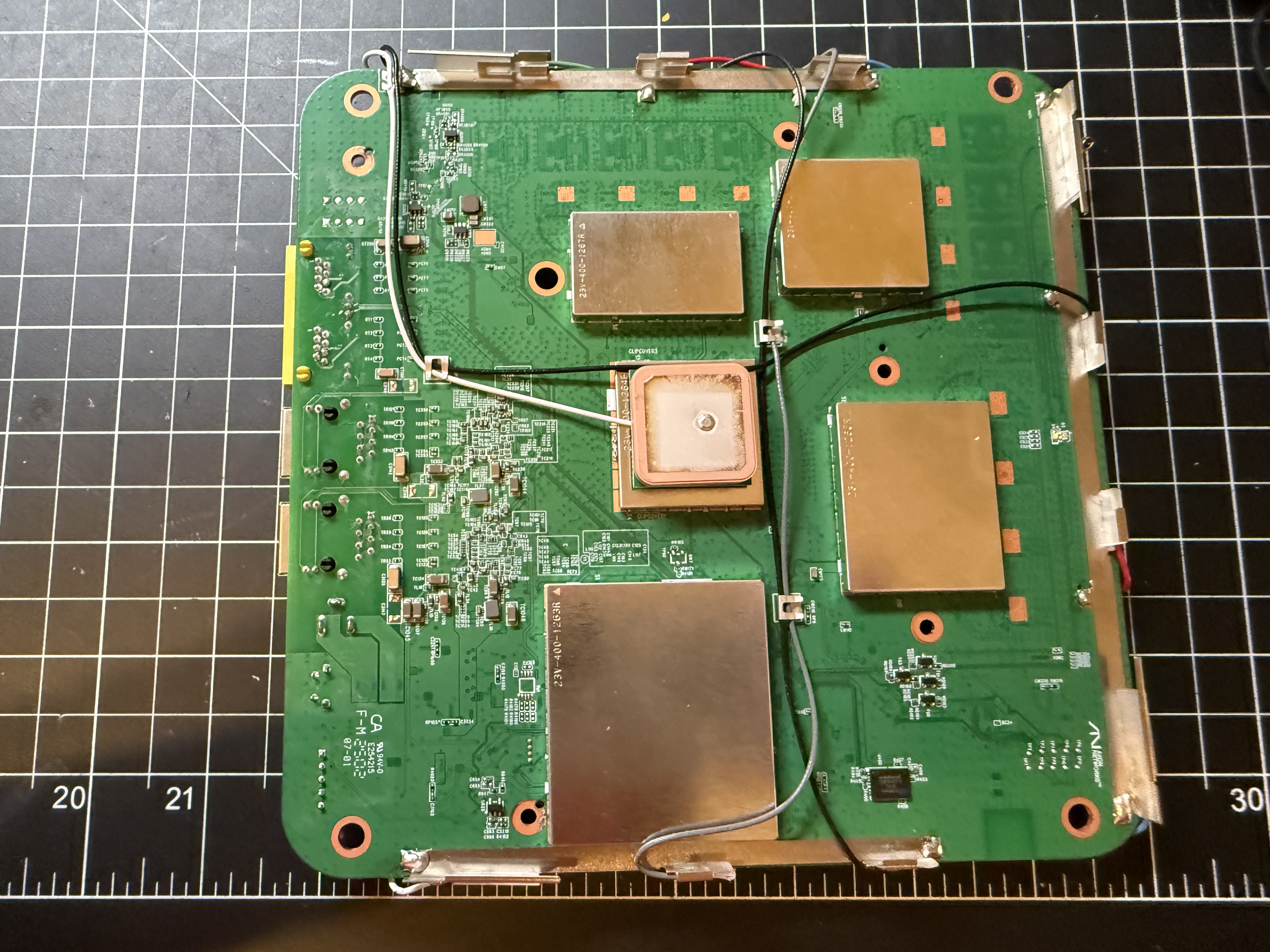
FCC and internal board photographs were used to separate the board’s several RF subsystems. Two test points, TP49 and TP50, were initially miscategorized before being correctly attributed to the Airoha AG3352Q GNSS section rather than the MG21.
The actual MG21 radio area is the small QFN32 package marked MG21, alongside a crystal, 2.4 GHz RF matching network and antenna path, and test points TP68, TP69, TP71, and TP72.
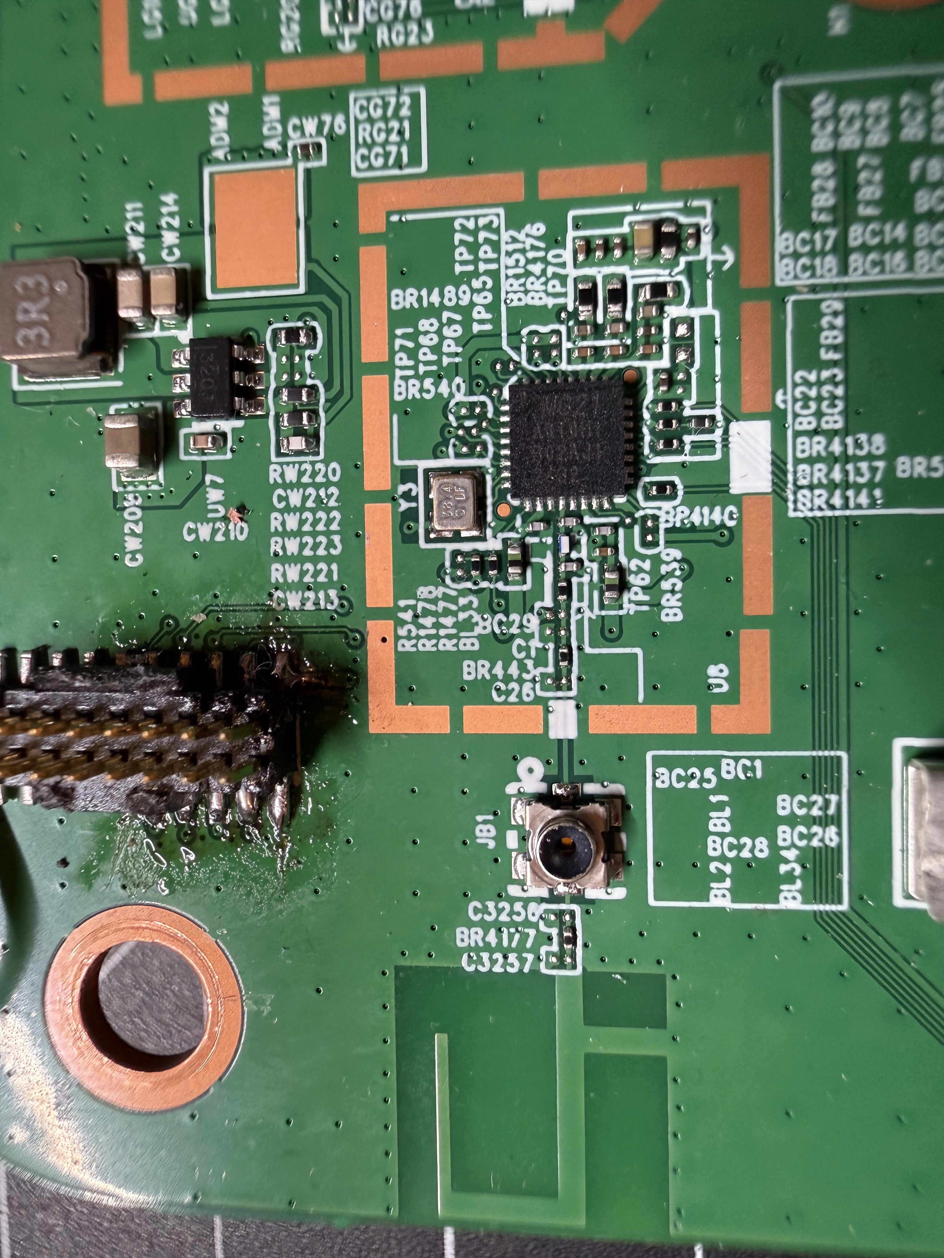
The first plan was to trace the MG21’s fixed debug pins directly from the QFN32 package to nearby test points:
QFN32 pin 18 / PA01 = SWCLK
QFN32 pin 19 / PA02 = SWDIO
QFN32 pin 20 / PA03 = SWO
QFN32 pin 9          = RESETn
QFN32 pin 27         = IOVDD / debugger voltage reference
That plan was superseded once an unpopulated 2×5 footprint labeled J10, sitting right next to the MG21, was recognized as a much stronger candidate: a complete Silicon Labs Mini Simplicity connector.
Turning the J10 hypothesis into a measured pinout
J10’s 2×5 form factor, roughly 1.27 mm pitch, and pin-1 mark resembled Mini Simplicity, but the photo-based orientation was treated only as a hypothesis. With the board unpowered, continuity was checked in a specific safe order before any debugger was connected:
- find pin 2 by continuity to ground;
- verify pin 3 to
RESETn; - verify pin 7 to
PA02/SWDIO; - verify pin 8 to
PA01/SWCLK; - test the PTI pair, then VCOM/SWO.
The distinctive pair J10-9 → PC05 and J10-10 → PC04 matched the EFR32xG21 reference mapping for PTI_FRAME/FRC_DFRAME and PTI_DATA/FRC_DOUT, which sharply increased confidence before the remaining pins (J10-4 → PA06, J10-5 → PA05, J10-6 → PA03) were measured and confirmed. All ten pins came back correct:
| J10 pin | Mini Simplicity function | EFR32MG21 destination | QFN32 pin |
|---|---|---|---|
| 1 | VTARGET sense | IOVDD | 27 |
| 2 | GND | GND | — |
| 3 | RESET | RESETn | 9 |
| 4 | VCOM_RX | PA06 | 23 |
| 5 | VCOM_TX | PA05 | 22 |
| 6 | SWO | PA03 / DBG_TDO_SWO | 20 |
| 7 | SWDIO | PA02 | 19 |
| 8 | SWCLK | PA01 | 18 |
| 9 | PTI_FRAME / FRC_DFRAME | PC05 | 6 |
| 10 | PTI_DATA / FRC_DOUT | PC04 | 5 |
Gemtek did not merely expose two SWD pads; they left a complete Silicon Labs production/development interface: SWD, reset, SWO, UART/VCOM, PTI, ground, and target-voltage sensing, in one 2×5 header.
Choosing a debugger
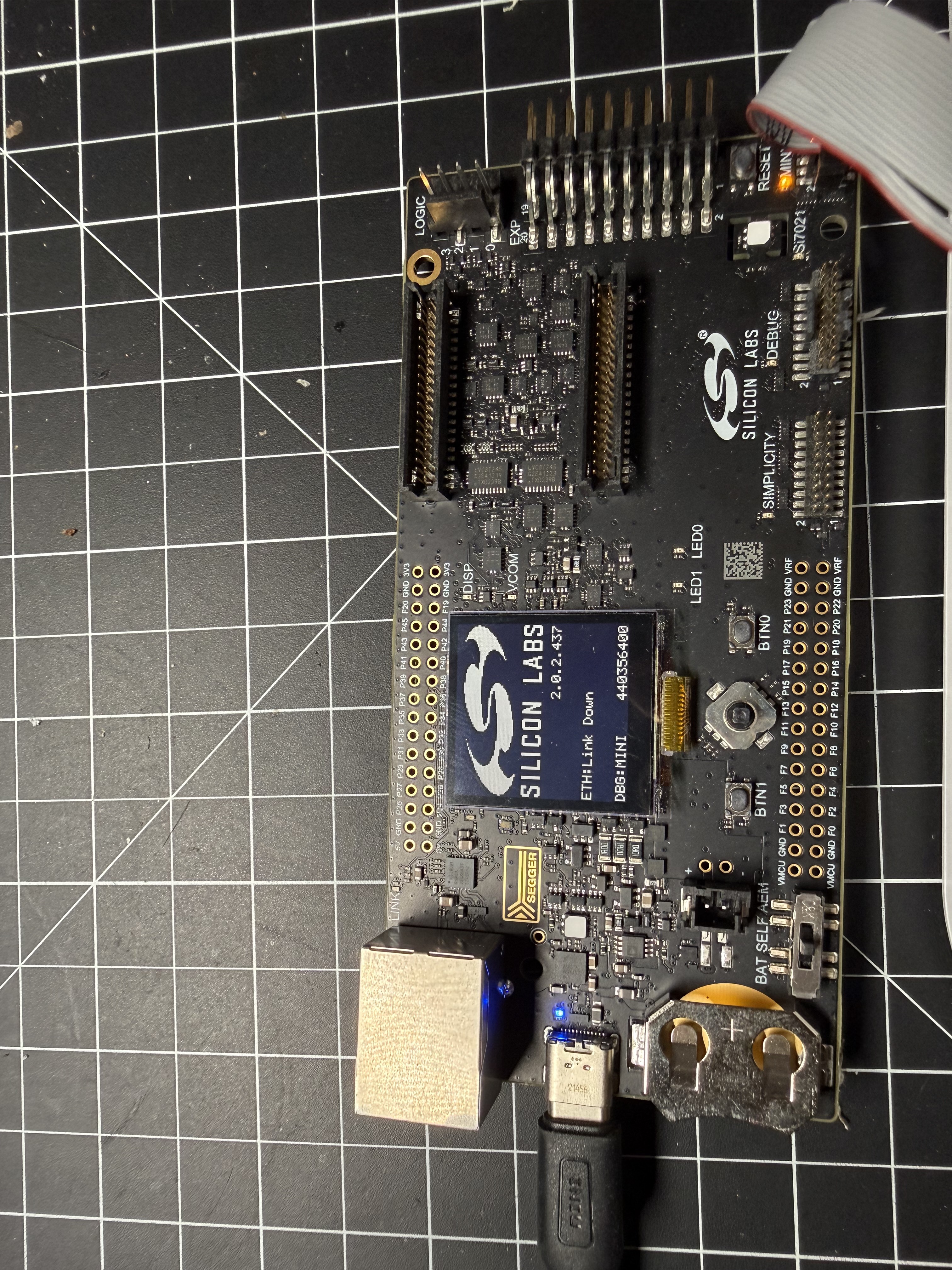
Three options were considered for connecting to J10: a generic J-Link, sufficient for SWD programming, register access, and breakpoints; the older BRD4001A WSTK reached through a BRD8010A/B/SLSDA001A adapter (not purely passive — it includes roughly 47 Ω series resistance and a MIC7300 VMCU/VTARGET mirror circuit); or a BRD4002-series Wireless Pro Kit, whose board-mounted MINI connector and debug mux expose SWD/SWO, VCOM, PTI, and voltage/AEM directly. The BRD4002 was used here, connected BRD4002 MINI ↔ 10-pin ribbon ↔ W1700K J10 in MINI mode. The W1700K stayed self-powered throughout; J10 pin 1 was treated only as a target-voltage reference, never as an invitation to power the router from the WSTK.
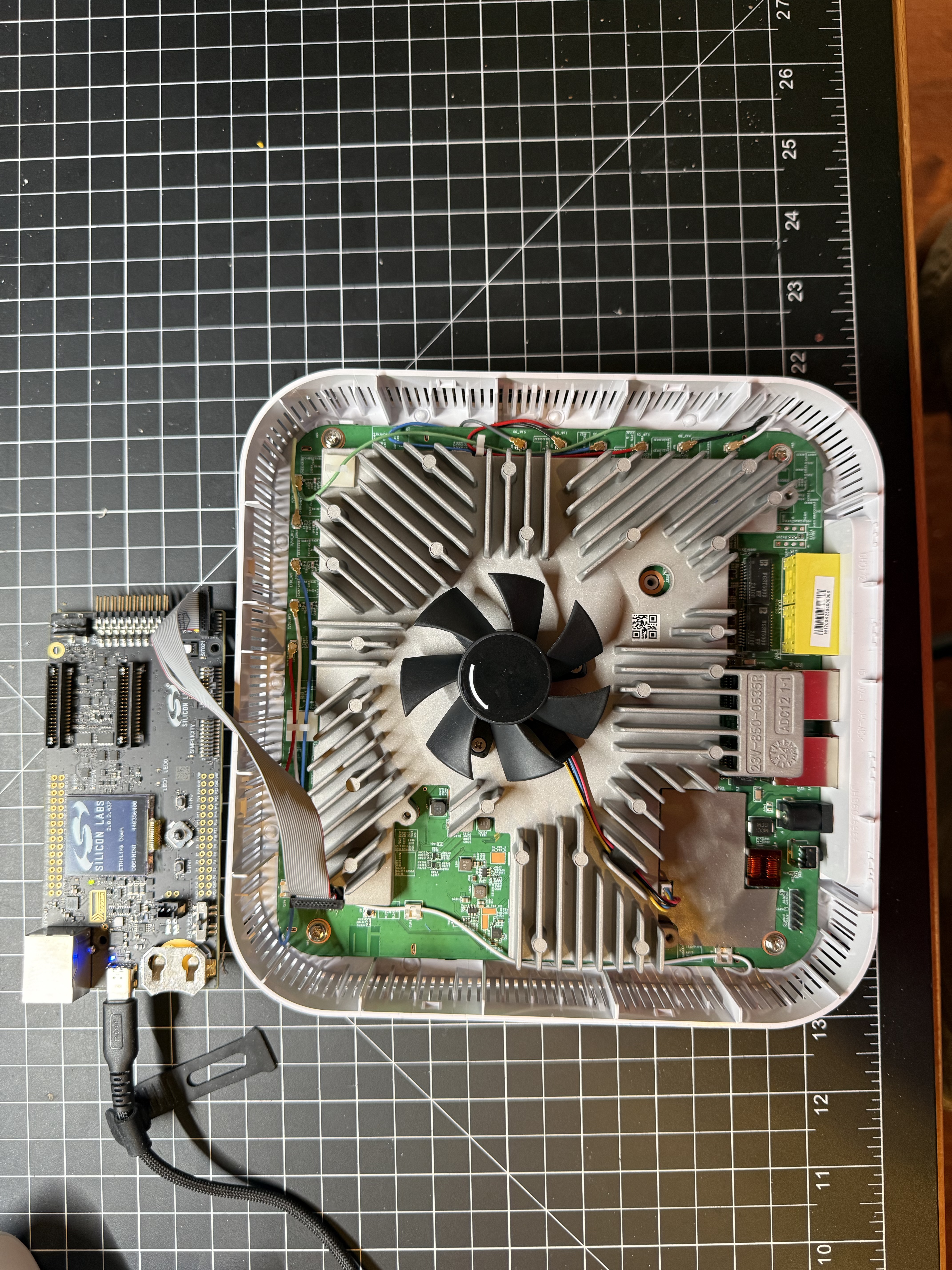
A generic J-Link remains entirely adequate for ordinary SWD flashing and debugging — it was, in fact, the tool used later for live crash debugging during Thread bring-up (see the Thread chapter). The WSTK’s advantage here was specifically its integrated VCOM/PTI/SWO access for full board characterization.
Cutting VCOM_RX/VCOM_TX out of the ribbon
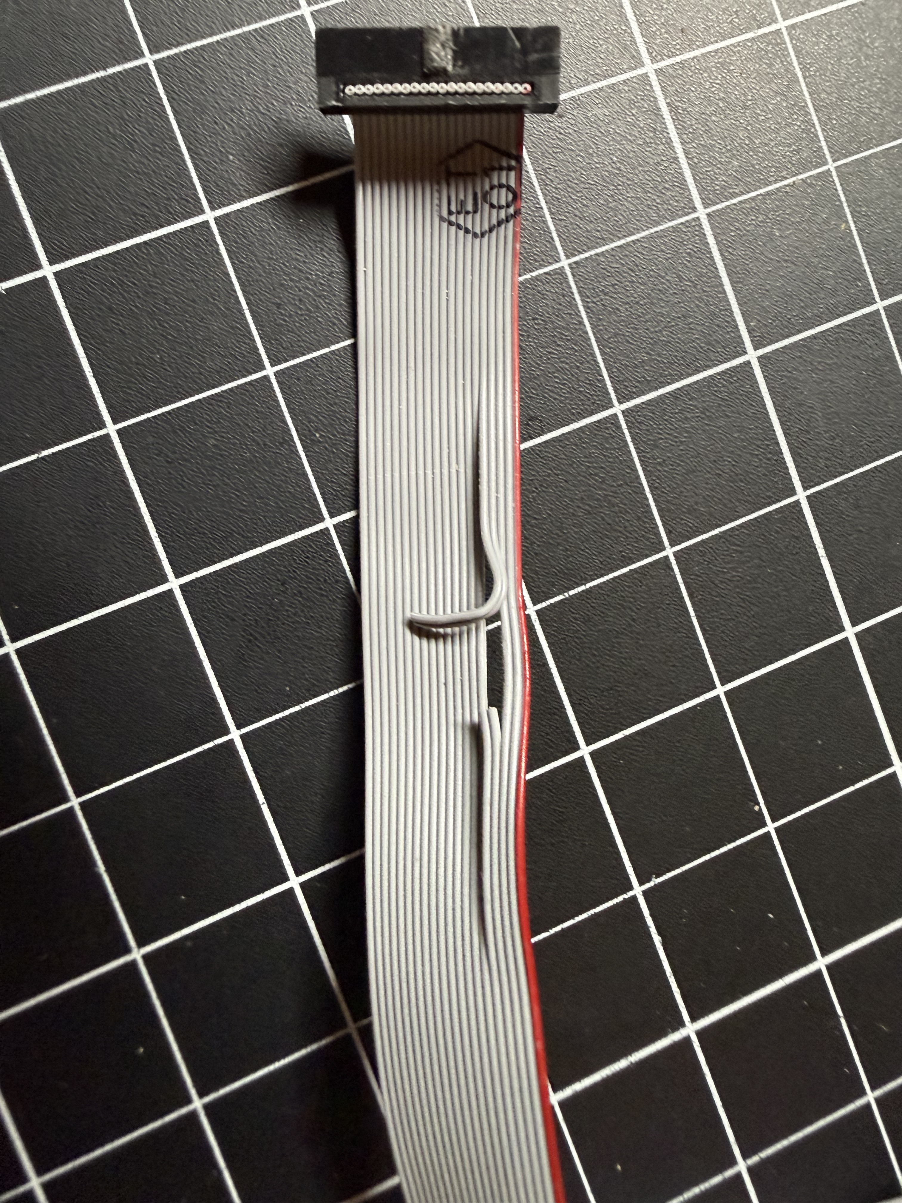
Pins 4 and 5 of the J10 connector, VCOM_RX/PA06 and VCOM_TX/PA05, are wired to the same two MG21 pins the AN7581 host uses as its own UART TX/RX. That’s normal for a Mini Simplicity interface — VCOM is meant to give the debugger its own serial console into the target — but it means the WSTK’s VCOM transceiver sits electrically in parallel with the AN7581’s UART, on the same two wires. With both attached at once, the WSTK’s VCOM output contended with (loaded down) the AN7581’s transmitter: AN7581-side byte counters still incremented, proving the host really was sending, but the MG21 never answered, because what actually reached its RX pin was a fight between two drivers rather than a clean signal.
The practical fix was to cut pins 4 and 5 out of the 10-pin Mini Simplicity ribbon cable entirely, leaving SWD, reset, PTI, ground, and target-voltage sensing intact on the debugger side while physically removing VCOM from the ribbon. That makes SWD debugging and running scripts over the AN7581’s own UART two genuinely independent things, usable at the same time, instead of a connect/disconnect dance every time the active side needed to switch. Before this cut, the workaround was to unplug the WSTK’s VCOM for every UART operation and reconnect it only to verify a flash write over SWD — workable, but tedious and easy to forget mid-session (exactly the bug documented later in this chapter, under mg21-flash-upload.sh’s defect list).
Identifying the exact silicon and its security state
Commander reported the part as:
EFR32MG21A010F512IM32-B
Silicon revision: B
Commander internal die revision: A1
(The final -B vs -BR suffix, which distinguishes tray from tape-and-reel packaging, cannot be recovered from a soldered chip.)
The security read was the single most consequential result of this whole phase:
Debug Lock:         Disabled
Device Erase:       Enabled
Secure Boot:        Disabled
This is the most permissive of the four conceptual security states that had been considered beforehand. In practical terms: the chip can be dumped in full and archived as a golden backup, restoring it to bone-stock condition at any time, and there’s no write limit or any other security gate standing in the way — no debug lock, no enforced secure-boot signature check on whatever application code gets written back.
Making redundant, auditable dumps
Before writing anything, full main flash, User Data, and DEVINFO were read out:
commander readmem --device EFR32MG21A010F512IM32 --region @mainflash --outfile w1700k-mg21-stock.bin
commander readmem --device EFR32MG21A010F512IM32 --region @userdata  --outfile w1700k-mg21-userdata.bin
commander readmem --device EFR32MG21A010F512IM32 --region @devinfo   --outfile w1700k-mg21-devinfo.bin
Two independent 524,288-byte main-flash reads (dump1.bin, dump2.bin) compared byte-for-byte identical. The golden main-flash dump’s SHA-256 is 978fbd3aa39ae142f88c6e9b1ccf95a5f08f594c3d03f3c3f71750935a7bfdb4.
Recovering the flash map from structural signatures
Static inspection of the dump, rather than any documentation, established the flash layout:
0x00000000  Gecko Bootloader vector table (size ~0x2794)
0x00004000  Bluetooth application vector table
0x00074000  NVM3-like page 1
0x00076000  NVM3-like page 2
0x00078000  NVM3-like page 3
0x0007A000  NVM3-like page 4
0x0007C000  NVM3-like page 5, ending at 0x0007DFFF
0x00080000  end of 512 KiB main flash
At 0x00002618, little-endian 0x5ECDB007 is Silicon Labs’ BOOTLOADER_MAGIC_MAIN. Parsing the surrounding table gave:
Bootloader table:    0x00002618
Bootloader version:  0x02010002
Bootloader size:     0x00002794
Application start:   0x00004000
Application end:     0x00080000
Capabilities:        0x001004F0
The capability bits decode as BOOTLOADER_UPGRADE, GBL, GBL_SIGNATURE, GBL_ENCRYPTION, PERIPHERAL_LIST, and COMMUNICATION, with STORAGE clear — characteristic of a standalone communication bootloader that streams an upgrade and writes it directly, rather than staging it in a storage slot first. GBL_SIGNATURE/GBL_ENCRYPTION are capability bits, not proof of enforced policy.
At 0x00035428, the application region contains the 16-byte ApplicationProperties magic 13 B7 79 FA C9 25 DD B7 AD F3 CF E0 F1 B6 14 B8, decoding to `Application type:
0x20 = APPLICATION_TYPE_BLUETOOTH_APP. Each of the five 8 KiB-aligned pages from 0x74000to0x7C000begins with the same 20-byte NVM3-style header,01 00 9A B2 01 00 00 D0 FE FF FF 0F FF FF FF FF 30 90 FF FF`, supporting a 40 KiB NVM3 allocation.
Live AN7581-to-MG21 UART characterization
Everything above came from static analysis. The next phase proved the live transport:
Airoha AN7581 / OpenWrt
    /dev/ttyS1, 115200 8N1, no RTS/CTS
    AN7581 TX -> J10-5 / PA05 / MG21 RX
    AN7581 RX <- J10-4 / PA06 / MG21 TX
    GPIO536        -> J10-3 / MG21 RESETn, active low
    GPIO537        -> MG21 Gecko Bootloader activation, active low
                         |
                         v
EFR32MG21 stock Bluetooth application or Gecko BGAPI UART DFU bootloader
Finding the right UART
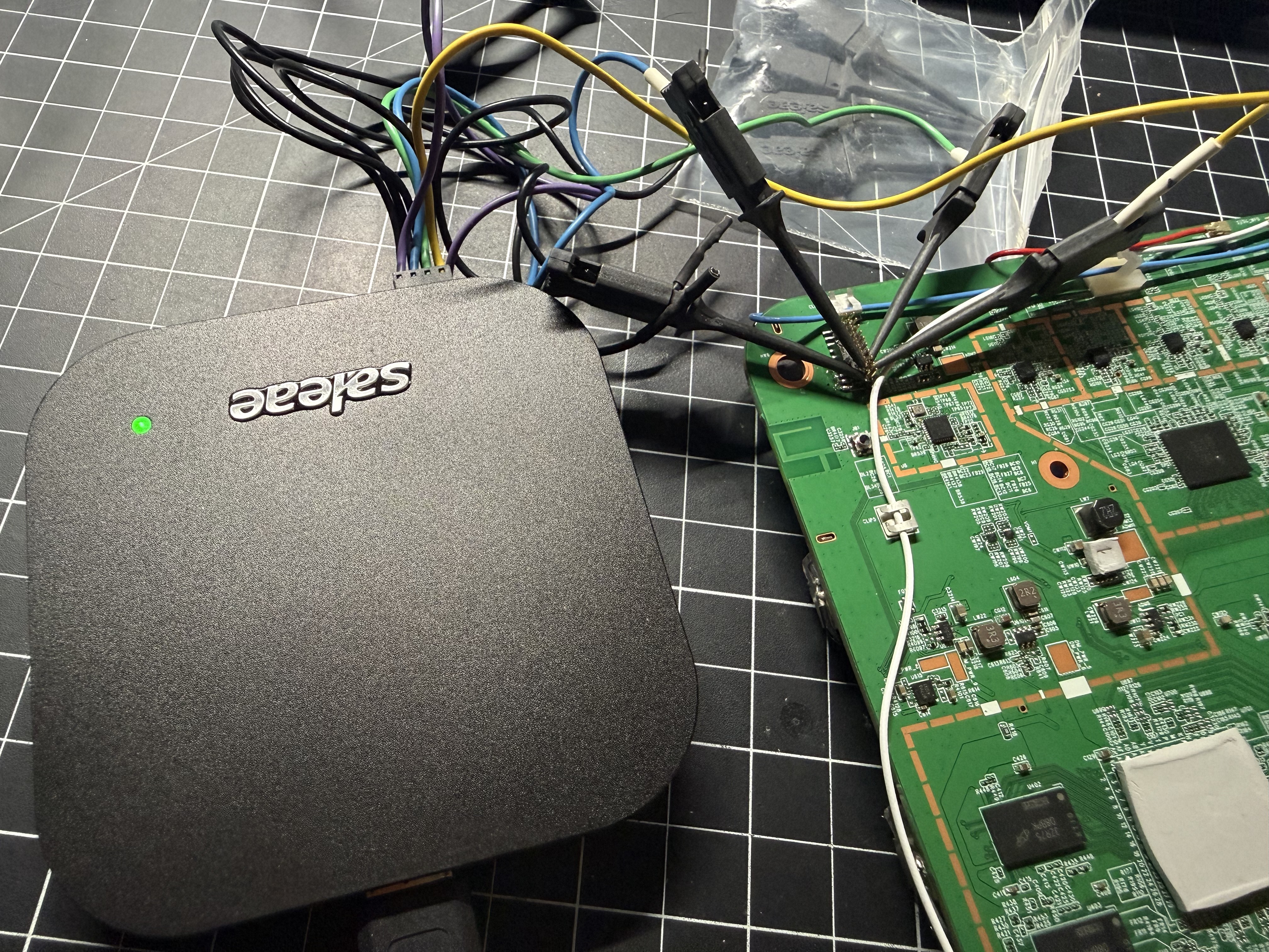
Kernel enumeration showed three serial ports: ttyS0 (the AN7581’s own console, not a candidate), and two more Airoha 16550 instances, ttyS1: 0x1fbf0300, IRQ 22, base_baud 460800 and ttyS2: 0x1fbe1000, IRQ 23, base_baud 460800, both device-tree compatible airoha,en7523-uart and both enabled. Device-tree inspection alone couldn’t disambiguate them — neither node referenced Bluetooth, Zigbee, MG21, or anything radio-related. Settling it required a physical test rather than more reading: with a Saleae Logic analyzer clipped onto J10-4 (MG21 TX) and J10-5 (MG21 RX), each candidate device was opened and written to in turn while watching for corresponding activity on those two logic channels. /dev/ttyS2 produced nothing. /dev/ttyS1 produced exactly the expected byte-for-byte traffic, decisively mapping the MG21 link to that device:
stty -F /dev/ttyS1 115200 cs8 -cstopb -parenb raw -echo -ixon -ixoff -crtsctsFinding the reset and bootloader GPIOs
No device-tree node, kernel-owned GPIO, Bluetooth/Zigbee/Thread daemon, or init script referenced the MG21 at all — RESETn and the bootloader-activation line had to be on some unclaimed, unnamed AN7581 GPIO, found only by systematically driving candidates while watching the UART. The AN7581 exposes its GPIOs as one large flat number space (in the high 500s for the block this project cared about), not small per-pin indices like GPIO0/GPIO1 — so the search was a genuine sweep, not a guess at a handful of obvious candidates.
The reset line was found first. Each otherwise-unclaimed GPIO (skipping ones already owned by the kernel for LEDs, the front-panel key, or PHY resets) was exported via sysfs, toggled low then high, while watching D0 on the logic analyzer for a pulse. GPIO536 was the one that moved: driving it low and releasing it produced a reset pulse on J10-3, followed by the MG21’s normal 22-byte sl_bt_evt_system_boot event on the UART — the same event a commander device reset through the WSTK independently produced, confirming the mapping.
With reset known, the bootloader-activation pin was found the same way, but gated on reset: for each remaining candidate GPIO, the scanner drove it low, pulsed GPIO536 (reset), then classified whatever came back on the UART. Every candidate except one just produced the same normal 22-byte application boot event — reset had happened, but the MG21 still came back up running its regular application. GPIO537 was different: holding it low through a reset produced an 8-byte event instead, A0 04 00 00 02 00 01 02, Silicon Labs’ BGAPI_EVENT_DFU_BOOT with the bootloader’s own version word embedded in it — proof the chip had entered the Gecko Bootloader instead of booting its application. That made GPIO537 conclusively the active-low bootloader-activation line. The full scan results and exact entry sequence are in the GPIO536/GPIO537 section below.
BGAPI command verification
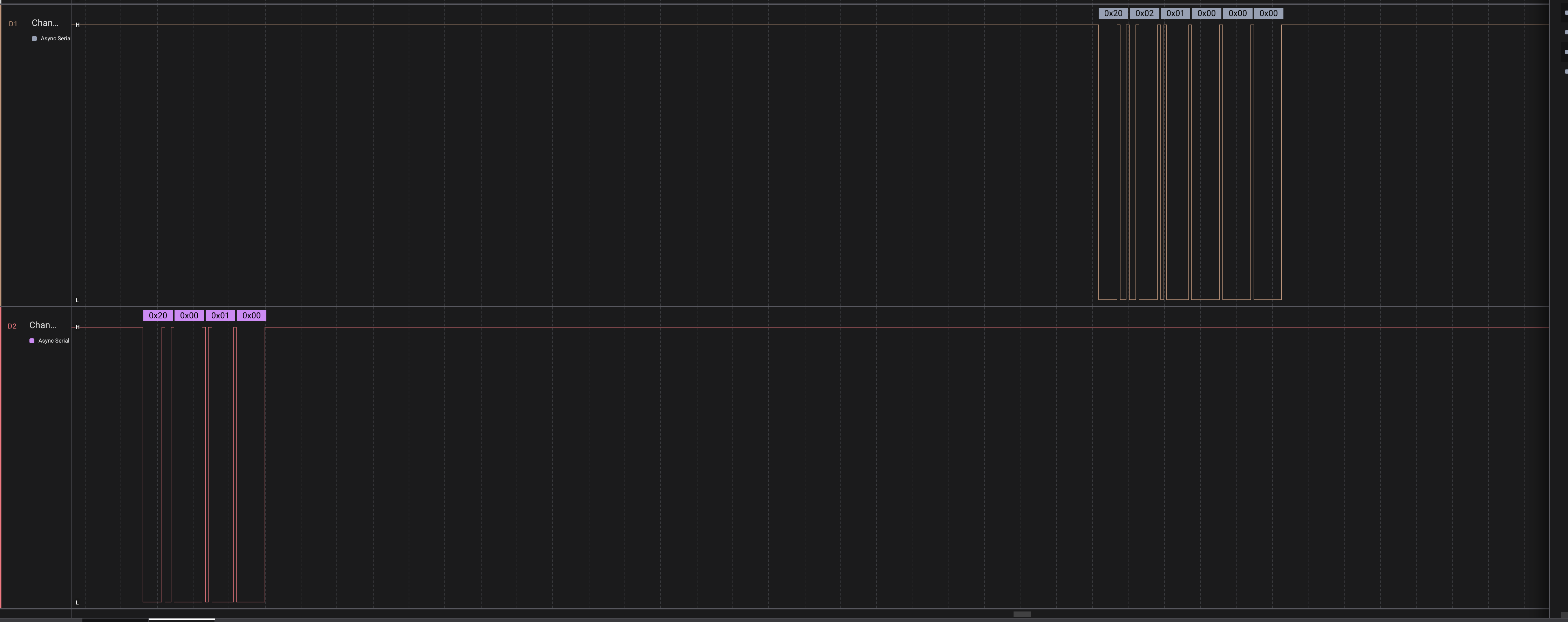 Saleae Logic capture: system_hello request/response.
Correct BGAPI exchanges captured on a Saleae Logic analyzer:
system_hello:
host -> MG21: 20 00 01 00
MG21 -> host: 20 02 01 00 00 00
system_get_version:
host -> MG21: 20 00 01 1B
MG21 -> host: 20 12 01 1B 00 00 04 00 02 00 01 00 56 01 00 00 00 00 99 51 60 7D
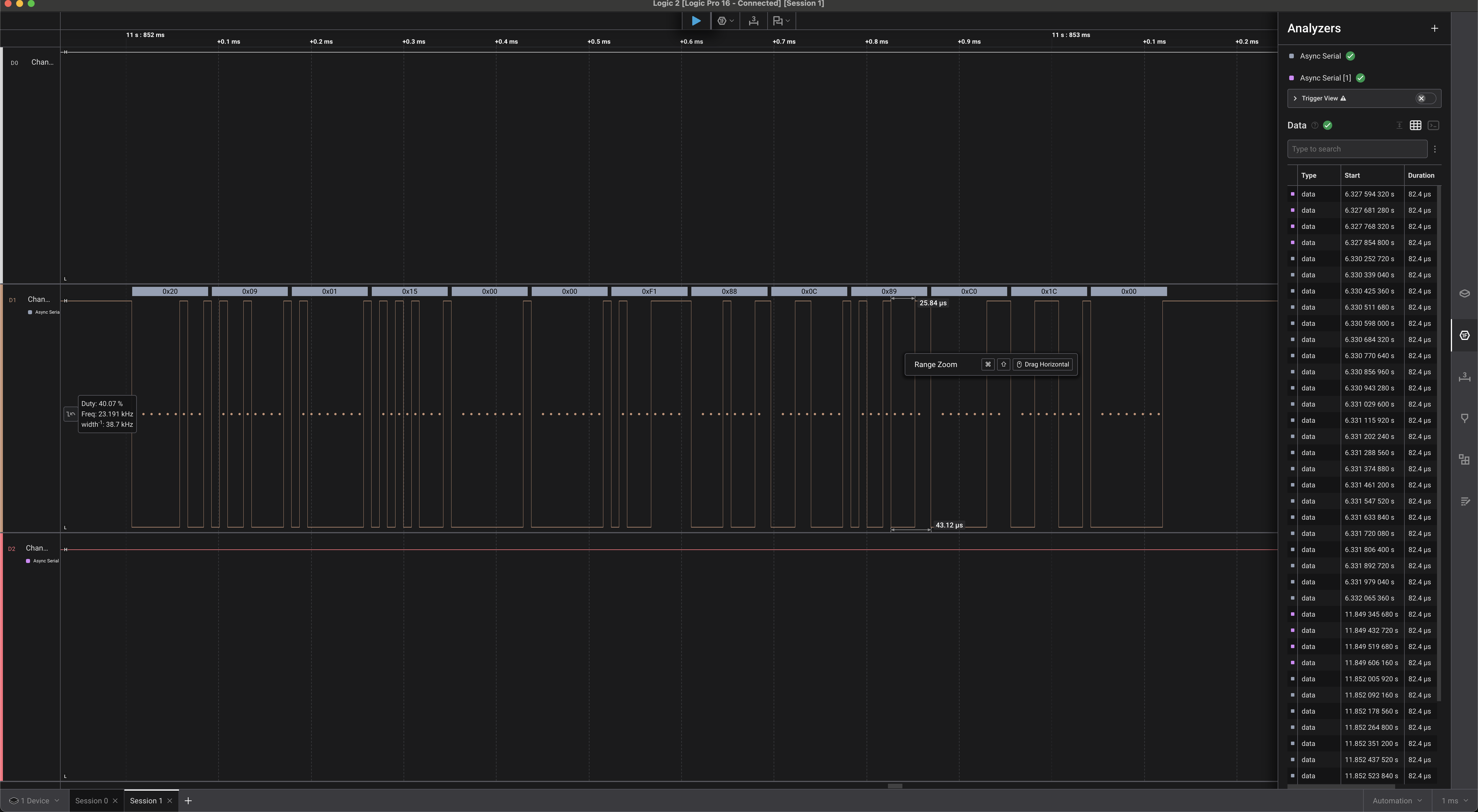
system_get_identity_address:
host -> MG21: 20 00 01 15
MG21 -> host: 20 09 01 15 00 00 F1 88 0C 89 C0 1C 00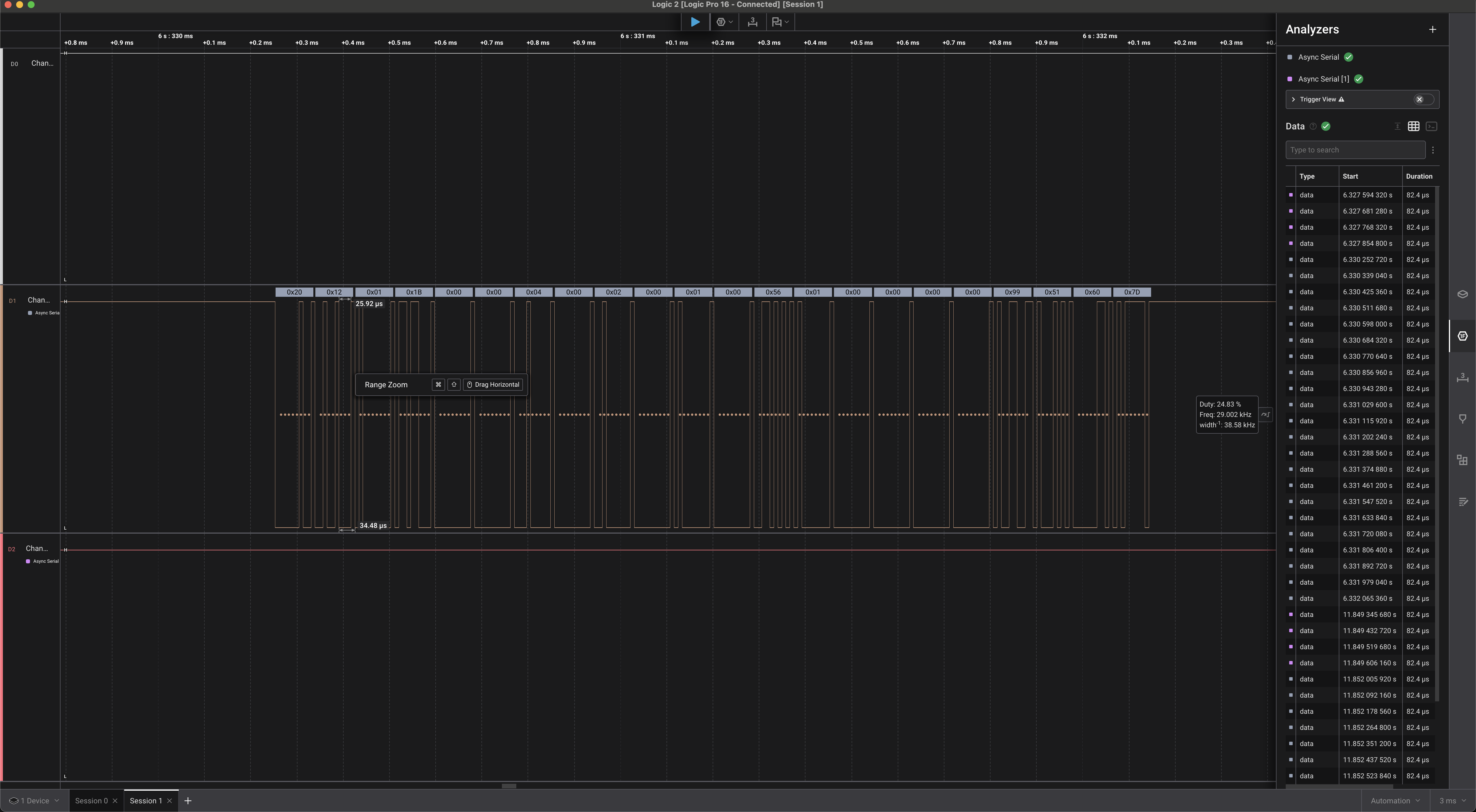 Saleae Logic capture: system_get_version response (4.2.1 build 342).
 Saleae Logic capture: system_get_identity_address response.
The factory Bluetooth stack identifies as 4.2.1 build 342, hash 0x7D605199, public address F1:88:0C:89:C0:1C.
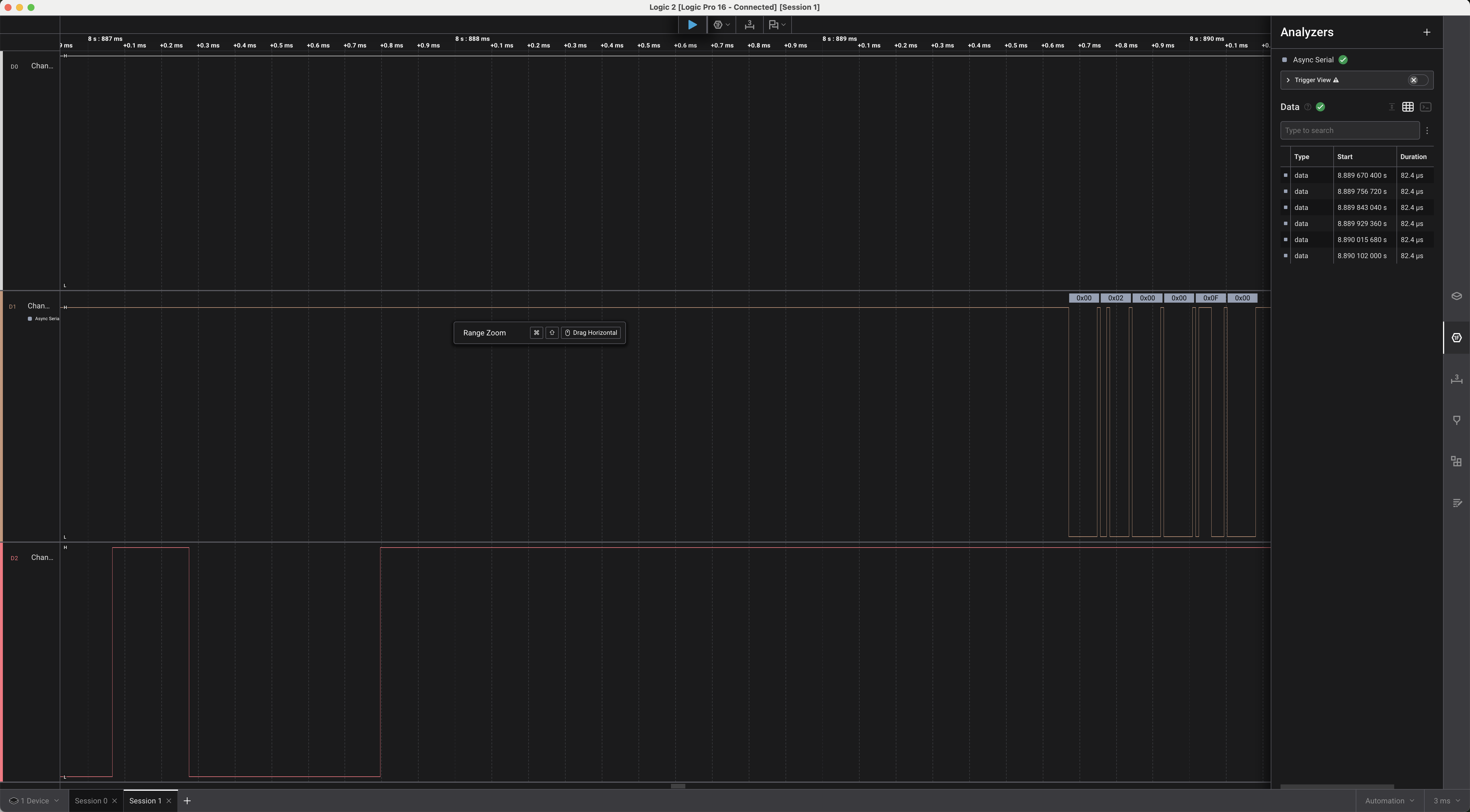 Saleae Logic capture: early host TX / MG21 response, captured while UART framing was still being established.
The normal boot event, and why software-only DFU entry failed
The repeatable normal application boot event is:
A0 12 01 00 04 00 02 00 01 00 56 01 00 00 00 00 01 01 99 51 60 7D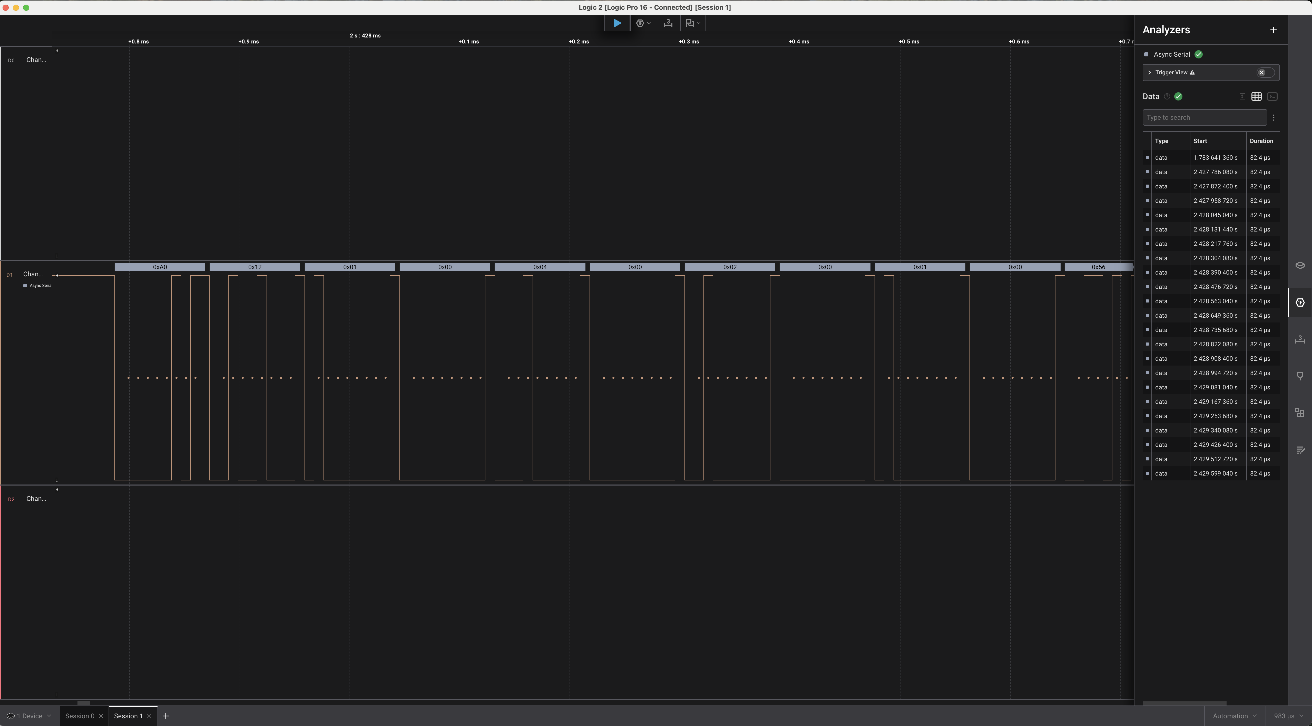 Saleae Logic capture: wide view of the normal 22-byte system_boot event.
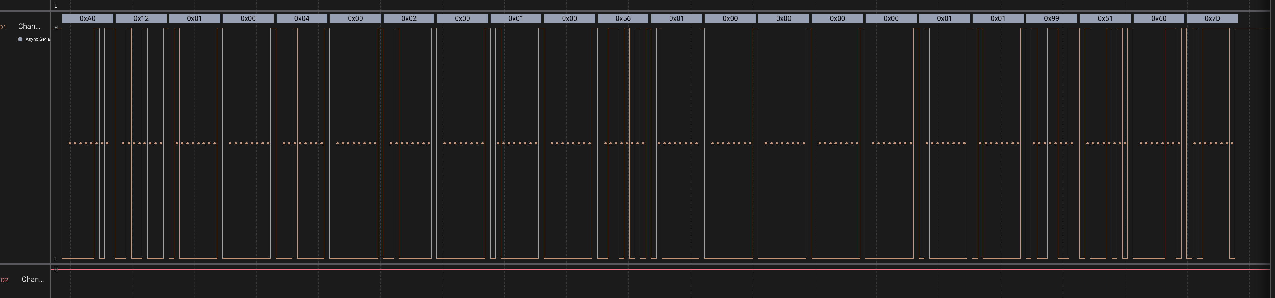 Saleae Logic capture: close decoded view of the same boot event.
Sending the ordinary application software-reset command, 20 01 01 01 00, produced a fresh boot event on the UART, but the RESETn line (D0) never pulsed — proving this reset is internal to the MG21.
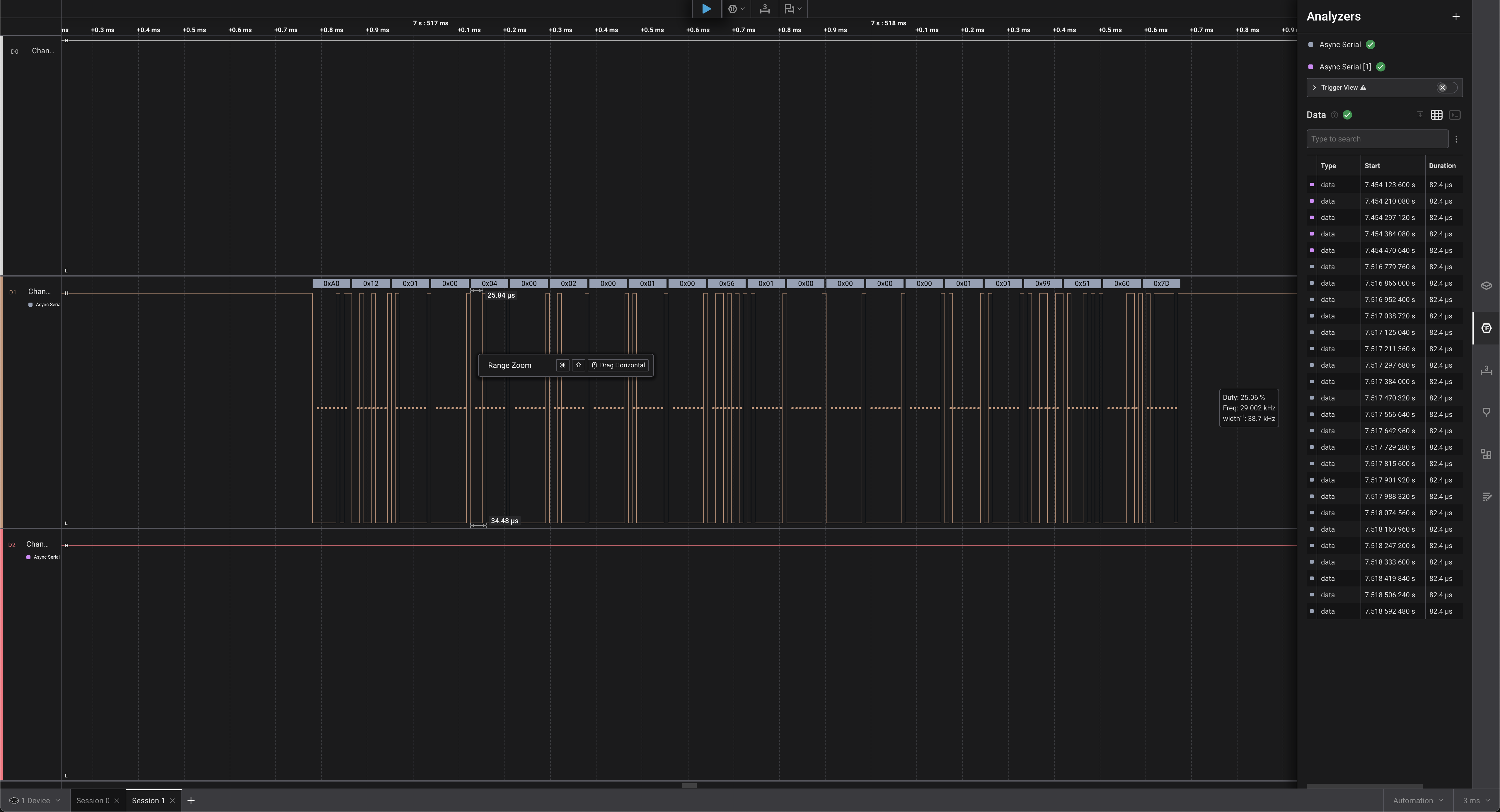 Saleae Logic capture: normal boot after internal software reset — D0 did not pulse.
Two DFU-entry attempts were tried and rejected. 20 01 00 00 01 is a malformed/DFU-class packet, not a valid application reset. The correct application-side system_reset with boot_in_dfu=1 is 20 01 01 01 01 — but on this factory image, it still returned the same normal application boot event rather than entering DFU.
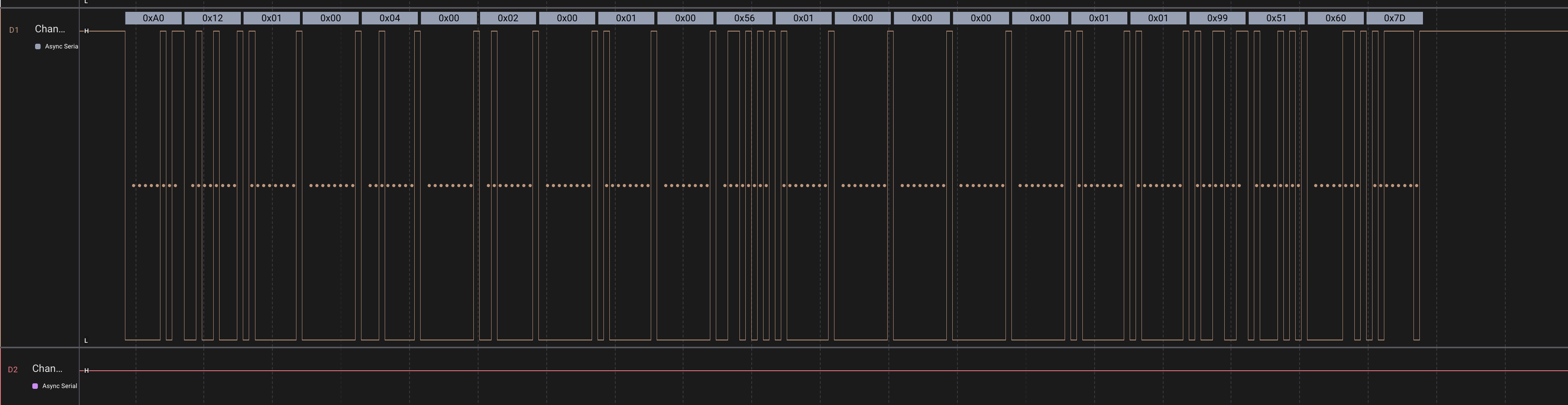 Saleae Logic capture: proof the software-only DFU-flag attempt still produced a normal app boot event.
The durable conclusion: the stock application provides no working software-only path into DFU. A dedicated hardware activation line is required, and that line remains available even after the application is replaced with Zigbee or Thread firmware — a fact the flashing tooling built for this project depends on.
GPIO536 and GPIO537
An automated scanner drove one candidate GPIO low, held GPIO536 low for one second to assert RESETn, released it, and classified the resulting boot event. Scan results:
GPIO513, GPIO514: busy / could not export
GPIO515–GPIO526: normal 22-byte Bluetooth boot event
GPIO527, GPIO528: busy / could not export
GPIO530, GPIO533, GPIO534, GPIO535: normal 22-byte Bluetooth boot event
GPIO537: 8-byte DFU boot event; scanner stopped immediately
The GPIO537 result was the exact DFU boot event A0 04 00 00 02 00 01 02, which Silicon Labs’ SDK defines as BGAPI_EVENT_DFU_BOOT, little-endian payload 0x02010002 — exactly matching the bootloader version already parsed from flash. GPIO537 is conclusively the active-low Gecko Bootloader activation line, and GPIO536 is active-low RESETn. The entry sequence:
GPIO537 low
GPIO536 low  (assert RESETn)
GPIO536 high (release RESETn)
keep GPIO537 low briefly while bootloader samples it
GPIO537 high/input
A bootloader-side 20 01 01 01 00 command then returned the device to the exact normal 22-byte application boot event, proving bidirectional bootloader control and recovery without ever writing flash.
GBL generation and the reverse-engineered UART DFU wire protocol
With entry/exit proven safe, the remaining open question was whether the factory bootloader would accept an unsigned, unencrypted community-built application image over this UART path — this was resolved by direct testing, twice, independently.
Wire protocol, read from the locally installed Silicon Labs bootloader source
Rather than infer the protocol purely from captures, the exact format was read directly from bootloader/platform/bootloader/communication/bgapi-uart-dfu/btl_comm_bgapi.h and btl_comm_bgapi_common.c. The frame header is { type(1B), len(1B), class(1B), command(1B) } followed by len payload bytes:
BGAPI_PACKET_TYPE_COMMAND = 0x20
BGAPI_PACKET_TYPE_EVENT   = 0xA0

BGAPI_PACKET_CLASS_DFU    = 0x00
BGAPI_PACKET_CLASS_SYSTEM = 0x01

DFU_RESET               = 0x00
DFU_FLASH_SET_ADDRESS    = 0x01   (deprecated/no-op)
DFU_FLASH_UPLOAD         = 0x02   (payload = [chunk_len:1B][chunk_data:≤254B])
DFU_FLASH_UPLOAD_FINISH  = 0x03   (no payload; imageCompleted && imageVerified checked here)

SYSTEM_RESET  = 0x01  (mode=0 -> boots app, mode=1 -> stays in bootloader)
BGAPI_EVENT_DFU_BOOT is {0xA0, 0x04, 0x00, 0x00} + 4-byte version (8 bytes total) — the same event already captured live. BGAPI_EVENT_DFU_BOOT_FAILURE(error) is sent unsolicited, before the normal boot event, whenever the reset reason is BOOTLOADER_RESET_REASON_BADAPP. The bootloader’s UART baud rate, 115200, is compiled into the binary itself (btl_uart_driver_cfg.h), and cannot be changed without reflashing the bootloader.
Building the GBL
Starting from the golden w1700k-mg21-stock.bin, the application region was extracted and packed with Commander:
commander convert app_full.bin --address 0x4000 --outfile app_full.s37
commander gbl create w1700k-generic-stock.gbl --device EFR32MG21A010F512IM32 --app app_full.s37
The final portable GBL covers 0x4000–0x74000 (the 8 KiB-page-aligned start of NVM3), so that flashing it deterministically overwrites that entire range on any target unit, regardless of that unit’s prior flash history, while never touching NVM3 or the bootloader. A single marker byte was patched at 0x40000 (a confirmed-unused, already-erased address) from 0xFF to 0xAA in a canary sibling GBL, so that a successful write could be distinguished from a no-op.
LZ4-compressed GBLs were tested and found not usably supported by this bootloader: chunk-level uploads mostly succeeded, but DFU_FLASH_UPLOAD_FINISH reliably rejected the compressed image with error 0x0046. Uncompressed GBLs are what this project distributes.
mg21-flash-upload.sh and its five debugged defects
The flashing tool was written as a POSIX/ash shell script, iterated through three versions (v1/v2/v3) while chasing five real bugs:
- WSTK VCOM electrical contention — with the WSTK’s VCOM still attached, the AN7581 UART TX byte counters advanced but the MG21 never answered; the WSTK’s VCOM was loading/contending on PA05/PA06. Fix: physically disconnect WSTK VCOM during UART work, reconnect only for SWD verification.
set -esilently swallowing errors — barekill "$pid"; wait "$pid"idioms returned exit 143 underset -e, aborting the whole script with no diagnostic output. Fixed by appending|| trueto every such call.dd bs=1 count=Nmissing fast ACKs — the DFU upload acknowledgement is near-instantaneous and was unreliably captured by a per-chunkddreader. Fixed by replacing it with one persistentcat "$DEV" > file &reader polled via growing file size.- Unsolicited
DFU_BOOT_FAILUREcorrupting the fixed-size boot-event read — once an interrupted write had left the appBADAPP, the bootloader entry sequence began prefixing an extra 6-byte failure event before the expected boot event. Fixed by detecting and stripping that prefix. - A local-variable name collision —
stream_wait()’s parameternsilently clobbered the outer chunk-loop’s ownn(POSIXashhas no scoped locals), making the byte-offset counter advance by only 6 bytes per 254-byte chunk. Fixed by prefixing every local inside that function with_sw_.
Performance improved from roughly one hour (v1, with an explicit 1-second sleep per chunk) to about 30 minutes (v2, sleep removed) to well under two minutes (v3, single persistent reader plus a fast no-sleep polling tier) for the full 458,828-byte, 1,807-chunk uncompressed image, at a theoretical raw-wire floor of about 40 seconds at 115200 baud.
Verified result
The first full successful UART DFU upload completed all 1,807 chunks, DFU_FLASH_UPLOAD_FINISH returned 20 02 00 03 00 00, and reset produced the exact known-good 22-byte application boot event. WSTK/SWD independently confirmed zero byte differences against the source image across 0x4000–0x74000, with the canary marker at 0x40000 reading back exactly 0xAA. A second, independent run using the bug-fixed v3 script reproduced the same result. This is the first empirically confirmed, independently-verified proof that this factory bootloader accepts an unsigned, unencrypted application GBL streamed entirely over UART — no WSTK, no SWD, no vendor signature.
Because the Gecko Bootloader partition (0x0–0x3FFF) is never touched by these app-only GBLs, and bootloader entry works regardless of whether the currently-installed application is valid, a failed or partial UART upload is recoverable by simply re-uploading a complete image — no WSTK is required for ordinary recovery, provided a distributed GBL never carries a --bootloader upgrade tag.
Stock BLE black box test: what the factory firmware can and can’t do
With flashing proven, the stock Bluetooth application itself was probed before being replaced. It turned out to be a Silicon Labs NCP-mode stack: the entire Bluetooth host stack runs on the MG21, and the AN7581 only issues BGAPI commands over UART — this will never appear to BlueZ as an hci0 device.
Sweeping the system class (0x01) confirmed at least 13 working commands (hello, get_random_data, halt, linklayer_configure, get_counters, data_buffer_write/clear, set_identity_address, get_identity_address, set_tx_power, get_tx_power_setting, set_lazy_soft_timer, get_version), plus start_bluetooth/stop_bluetooth present but locked (SL_STATUS_NOT_AVAILABLE). Every probed command in GAP class 0x03 returned the identical generic NOT_SUPPORTED response that an entirely nonexistent class also returned, so the black-box method could not distinguish “GAP compiled out” from “GAP disabled” — but no live evidence of GAP, Connection, or GATT functionality was found either way.
The practical conclusion: this exact stock firmware is a deliberately minimal identification/diagnostic image. Scanning, advertising, or connecting over BLE on this hardware requires custom firmware — which is the subject of the next chapter.