Control hardware from any computer. One USB cable, pure Python. The Doer USB GPIO Board plugs into a Windows, macOS or Linux computer over USB-C and gives it 28 Raspberry Pi-style GPIO pins, with digital I/O, hardware PWM, analog input and I2C. You drive it from Python with the open-source DoerGPIO library, using RPi.GPIO-style calls.
Buy the board · DoerGPIO on PyPI · Docs on GitHub
On this page: Features · Demo · Get started · Usage · Specs · Pinout · Firmware · Troubleshooting · FAQ · Build story · Resources
Features
- Cross-platform. Works with Windows, macOS and Linux. The board appears as a USB-serial port (CH340 bridge), and the library finds it automatically, so there is no port to configure.
- Raspberry Pi-style API.
setup(),input()andoutput()work the way they do in RPi.GPIO, and the pin numbers are the GPIO numbers printed on the board’s pinout label. - Digital, PWM, ADC and I2C. All 28 pins do digital input and output with configurable pull-up or pull-down. 8 pins have hardware PWM, 8 pins have a 12-bit analog input, and one I2C controller can be routed to either of two pin pairs.
- Open source. The Python library and the STM32 firmware are GPL-3.0 licensed and on GitHub.
It is built for makers who want to blink an LED, control a motor through a suitable external motor driver, or read a sensor straight from a laptop without setting up a Raspberry Pi; for rapid prototyping, where you script hardware tests on your development machine; and for teaching GPIO concepts with plain Python on any classroom computer. It can also add extra GPIO pins to a Raspberry Pi.
Demo
In the demo I connect an LED to the board and write a few lines of Python to make it blink.
The video also has its own page in Videos, or you can watch it on YouTube.
Get started
1. Install the Python library
DoerGPIO needs Python 3.9 or newer. It installs pyserial automatically.
pip install DoerGPIOOn some systems the command is pip3, or, if pip is not on your PATH, python -m pip install DoerGPIO.
2. Connect the board
Plug the board into a USB port with a data-capable USB-C cable. It shows up as a CH340 USB-serial device (USB ID 1a86:7523). Whether a driver is already available depends on your operating system and its version.
If your computer does not detect the board, see Troubleshooting.
3. Run your first script
This blinks an LED on GPIO 17 five times, then reads GPIO 22 with its pull-up resistor enabled:
from DoerGPIO import GPIO
import time

GPIO.setup(17, GPIO.OUT)            # GPIO 17 as output
for _ in range(5):
    GPIO.output(17, GPIO.HIGH)
    time.sleep(0.5)
    GPIO.output(17, GPIO.LOW)
    time.sleep(0.5)

GPIO.setup(22, GPIO.IN, pull_up_down=GPIO.PUD_UP)
print("GPIO 22:", GPIO.input(22))
When the library is imported it scans the USB ports, connects to the first Doer USB GPIO Board it finds and prints the board’s hardware and software version. There is no GPIO.setmode() call: the library always uses the GPIO numbers 0–27 from the pinout label.
Usage
Digital input and output
Any of the 28 pins can be an input or an output.
from DoerGPIO import GPIO

GPIO.setup(17, GPIO.OUT)                     # output, starts LOW
GPIO.setup(27, GPIO.OUT, initial=GPIO.HIGH)  # output, starts HIGH
GPIO.output(17, GPIO.HIGH)                   # GPIO.HIGH, 1 or True

GPIO.setup(22, GPIO.IN)                              # input, pull-up by default
GPIO.setup(23, GPIO.IN, pull_up_down=GPIO.PUD_DOWN)  # input with pull-down
GPIO.setup(24, GPIO.IN, pull_up_down=GPIO.PUD_OFF)   # input, no pull resistor
print(GPIO.input(22))                                # 0 or 1
GPIO.setup() also accepts a list of pins, for example GPIO.setup([5, 6, 13], GPIO.OUT).
PWM
PWM works on GPIO 4, 9, 10, 16, 18, 20, 22 and 26.
from DoerGPIO import GPIO
import time

GPIO.setup(10, GPIO.PWM)
GPIO.pwm_set_frequency(10, 1000)   # set the frequency first (Hz)
for duty in range(0, 101, 10):     # duty cycle: whole-number percent, 0–100
    GPIO.pwm_set_duty(10, duty)
    time.sleep(0.2)
GPIO.pwm_set_duty(10, 0)
Things to know:
- Duty cycle is a whole-number percentage from 0 to 100. Fractions such as
0.5are read as 0 %, and values above 100 are treated as 100 %. - Set the frequency before the duty cycle. Changing the frequency resets the duty cycle to 0 on that pin.
- Some pins share a frequency. GPIO 4 and 22 share one timer, and GPIO 9, 18 and 26 share another. Changing the frequency on one of them changes it on the others in its group and resets their duty cycles. GPIO 10, 16 and 20 each have their own timer.
- The default frequency is 1 kHz. The supported frequency range is listed in Specs.
Analog input (ADC)
Analog input works on GPIO 0, 9, 10, 11, 14, 15, 18 and 26. Read it with GPIO.adc_read(), not GPIO.input():
from DoerGPIO import GPIO

GPIO.setup(26, GPIO.ADC)
value = GPIO.adc_read(26)   # 0–4095 (12-bit)
print("ADC on GPIO 26:", value)
The ADC reference voltage, and so the formula for converting a reading to volts, is still being confirmed.
I2C
The board has one hardware I2C controller that can be routed to either of two pin pairs. Only one route is active at a time.
| Bus | SCL | SDA | Note |
|---|---|---|---|
1 | GPIO 16 | GPIO 20 | Shares pins with PWM on GPIO 16 and 20 |
2 | GPIO 3 | GPIO 2 |
from DoerGPIO import GPIO

if GPIO.i2c_init(1):                               # bus 1: SCL = GPIO 16, SDA = GPIO 20
    print([hex(a) for a in GPIO.i2c_scan(1)])      # addresses of devices found

# Read 2 bytes from register 0x00 of the device at address 0x48 (use your device's values)
data = GPIO.i2c_read_reg(1, 0x48, 0x00, 2)
I2C needs DoerGPIO 1.1 and firmware v0.2. Check the software version the library prints when it connects; see Firmware.
Cleaning up
In DoerGPIO 1.1, GPIO.cleanup() exists for RPi.GPIO compatibility but does not change any pin. Pins keep their last state after your script ends, so set outputs back to GPIO.LOW yourself if that matters for your circuit.
API reference (DoerGPIO 1.1)
GPIO.setup(pin, mode, pull_up_down=None, initial=0): configure a pin or a list of pins; see Digital input and output for the defaultsGPIO.output(pin, value): drive an output HIGH or LOWGPIO.input(pin): read a digital input; returns 0 or 1GPIO.pwm_set_frequency(pin, hz): set the PWM frequency in Hz (resets the duty cycle to 0)GPIO.pwm_set_duty(pin, percent): set the PWM duty cycle, whole number 0–100GPIO.adc_read(pin): read an analog input; returns 0–4095GPIO.i2c_init(bus=1): select and start I2C route 1 or 2; returnsTrueon successGPIO.i2c_scan(bus=1): list the addresses of devices that answerGPIO.i2c_write(bus, addr, data)/GPIO.i2c_read(bus, addr, length): raw I2C write / readGPIO.i2c_write_reg(bus, addr, reg, data)/GPIO.i2c_read_reg(bus, addr, reg, length): register write / readGPIO.cleanup(): no effect in 1.1 (kept for compatibility)
Constants: GPIO.IN, GPIO.OUT, GPIO.PWM, GPIO.ADC, GPIO.HIGH, GPIO.LOW, GPIO.PUD_UP, GPIO.PUD_DOWN, GPIO.PUD_OFF.
Specs
The board is built around an STM32 microcontroller. Its firmware is written in C with STM32CubeIDE and is open source.
| Item | Value |
|---|---|
| Microcontroller | STM32F070 (Arm Cortex-M0); exact variant (C6 or CB) to be confirmed |
| USB connection | USB-C; USB-serial through a CH340 bridge (USB ID 1a86:7523) |
| Drivers | Driver availability depends on the OS and its version; to be confirmed |
| GPIO pins | 28 configurable pins, GPIO 0–27 |
| Pull resistors | Configurable pull-up / pull-down on all pins (inputs default to pull-up) |
| PWM pins | 8 pins: 4, 9, 10, 16, 18, 20, 22, 26 |
| PWM duty cycle | Whole-number percent, 0–100 |
| PWM frequency | Default 1 kHz; supported range to be confirmed (lower limit about 15 Hz: a source-derived estimate from firmware v0.2, not hardware-verified) |
| ADC pins | 8 pins: 0, 9, 10, 11, 14, 15, 18, 26 |
| ADC resolution | 12-bit (0–4095) |
| I2C | 1 controller, two pin routes: GPIO 16/20 or GPIO 3/2 |
| Serial link | 230400 baud |
| Platforms | Windows · macOS · Linux |
| Python | 3.9+; pip install DoerGPIO (library 1.1) |
| Versions | Hardware 0.2; firmware v0.2 |
| Firmware language | C (STM32CubeIDE) |
| License | GPL-3.0 (library: GPL-3.0-or-later) |
Pinout
The GPIO numbers below are the ones printed on the pinout label and used in code. Every pin does digital input and output.
| GPIO | PWM | ADC | Notes | MCU pin |
|---|---|---|---|---|
| 0 | ✓ | PA1 | ||
| 1 | PB12 | |||
| 2 | I2C bus 2 SDA | PB7 | ||
| 3 | I2C bus 2 SCL | PB6 | ||
| 4 | ✓ | PWM frequency shared with GPIO 22 | PA8 | |
| 5 | PA12 | |||
| 6 | PA13 | |||
| 7 | PF1 | |||
| 8 | PB5 | |||
| 9 | ✓ | ✓ | PWM frequency shared with GPIO 18, 26 | PA6 |
| 10 | ✓ | ✓ | Own PWM timer | PA7 |
| 11 | ✓ | PA5 | ||
| 12 | PF0 | |||
| 13 | PA14 | |||
| 14 | ✓ | PA2 | ||
| 15 | ✓ | PA3 | ||
| 16 | ✓ | Own PWM timer; I2C bus 1 SCL | PB8 | |
| 17 | PB15 | |||
| 18 | ✓ | ✓ | PWM frequency shared with GPIO 9, 26 | PB1 |
| 19 | PA15 | |||
| 20 | ✓ | Own PWM timer; I2C bus 1 SDA | PB9 | |
| 21 | PB10 | |||
| 22 | ✓ | PWM frequency shared with GPIO 4 | PA11 | |
| 23 | PB2 | |||
| 24 | PB3 | |||
| 25 | PB4 | |||
| 26 | ✓ | ✓ | PWM frequency shared with GPIO 9, 18 | PB0 |
| 27 | PB14 |
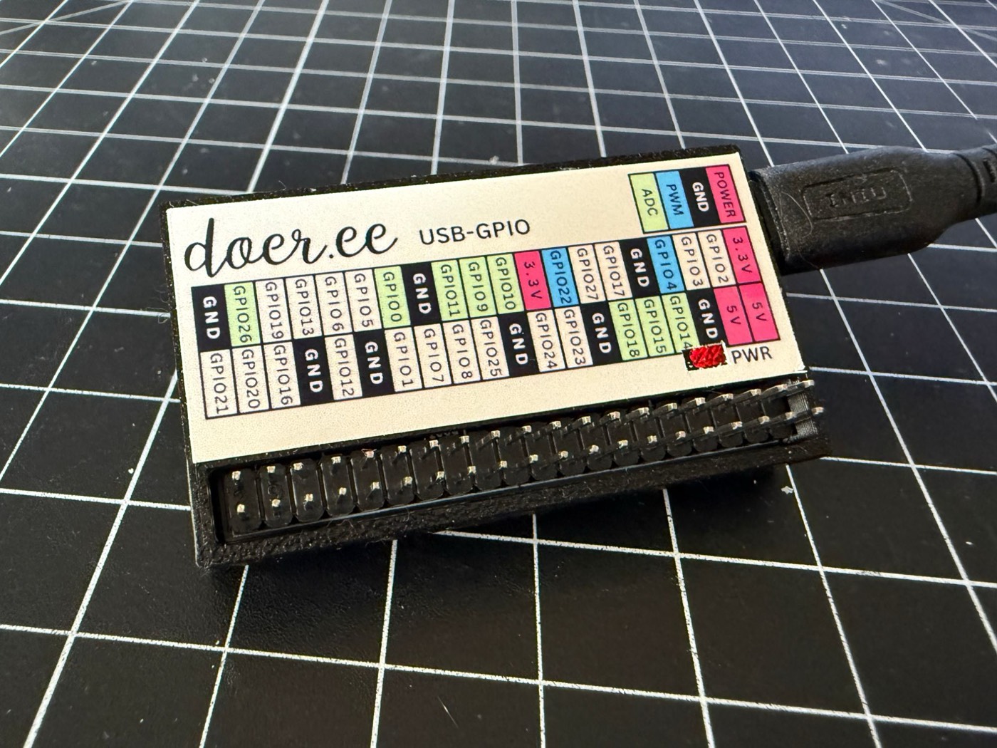
The MCU pins come from the firmware v0.2 source. Where each GPIO, 5 V, 3.3 V and GND pin sits on the 40-pin header is shown on the board’s pinout label; a printable header diagram will be added here once it has been checked against the schematic.
Firmware
The board runs open-source firmware, DoerGPIO_FW, written in C with STM32CubeIDE. The current release is v0.2, which reports itself as DoerGPIO_HW0.2_SW0.2 and adds I2C support.
Firmware updates
Which boards this applies to
| Requirement | Status |
|---|---|
Hardware version 0.2 (reported as DoerGPIO_HW0.2_…) | To be confirmed per batch |
| MCU variant: STM32F070, C6 or CB | To be confirmed |
| UART bootloader present and matching on all batches, including boards shipped before Feb 2026 | To be confirmed |
Firmware image v0.2 (DoerGPIO_FW.bin, 37,360 bytes) | Published; board compatibility to be confirmed |
| I2C: DoerGPIO 1.1 with firmware v0.2 | Confirmed from source |
How updates work
The board has a small UART bootloader. For a short moment after power-up it listens for an update request. The upload_fw.py tool from the firmware repository waits for the board to be plugged in, sends that request, and uploads the new image in checked chunks; the board then restarts. The original Doer USB GPIO page described this flow. We will publish step-by-step instructions here once the requirements above are confirmed.
Check your version
The DoerGPIO library prints the board’s hardware and software version every time it connects. The port name depends on your system (for example COM3 on Windows or /dev/ttyUSB0 on Linux):
Doer GPIO board Found on port: /dev/ttyUSB0
Hardware Version: 0.2
Software Version: 0.2
Note both numbers when you contact support. A software version of 0.2 is needed for I2C.
Source and building
The firmware source, the bootloader and the upload tool are in the DoerGPIO_FW repository, with release notes on its releases page. The application builds in STM32CubeIDE and the bootloader with make; see the repository README for details.
Troubleshooting
“Doer GPIO board is not detected.” The library looks for a USB-serial device with the ID 1a86:7523. Check that:
- the USB-C cable carries data (some cables are charge-only);
- your system shows a new serial port when you plug the board in. If it does not, install the CH340 driver from WCH, the chip’s maker. Per-OS details are being confirmed.
When the board is not found, the library prints this message and waits for you to press Enter before it exits. Keep that in mind if you start scripts without a terminal.
Another CH340 device is plugged in. Many USB-serial adapters and Arduino-compatible boards use the same CH340 chip. The library connects to the first matching device it finds, so unplug the others while you use the board.
The port is busy. Close serial monitors and other programs that may have the port open, then run your script again.
Permission denied on Linux. Add your user to the dialout group, then log out and back in:
sudo usermod -a -G dialout $USERWrong Board Version, contact customer support at cs@doer.ee The library printed this because the board answered with an unexpected version string. Contact hi@doer.ee with the output you saw.
AttributeError for setmode or BCM. Code written for the original example used import DoerGPIO as GPIO and GPIO.setmode(GPIO.BCM). Change the import to from DoerGPIO import GPIO and delete the setmode line.
FAQ
Which operating systems are supported?
Windows, macOS and Linux. The board connects as a USB-serial device through a CH340 bridge. Whether a driver is already available depends on the operating system and its version; this is still to be confirmed. See Get started.
How do I install the Python library?
Run pip install DoerGPIO in your terminal. Python 3.9 or newer is required. The library finds the board over USB automatically, so there is no port to select.
Which pins support PWM and ADC?
PWM: GPIO 4, 9, 10, 16, 18, 20, 22, 26. ADC: GPIO 0, 9, 10, 11, 14, 15, 18, 26. All 28 pins support digital I/O with configurable pull-up and pull-down resistors. See the Pinout table.
Which pins are used for I2C?
Bus 1 uses GPIO 16 (SCL) and GPIO 20 (SDA); bus 2 uses GPIO 3 (SCL) and GPIO 2 (SDA). They are two routes for the same controller, so use one at a time. I2C needs firmware v0.2 and DoerGPIO 1.1.
What unit does the PWM duty cycle use?
A whole-number percentage from 0 to 100. Set the frequency first, because changing it resets the duty cycle to 0.
My code uses GPIO.setmode(GPIO.BCM). Do I need it?
No. DoerGPIO has no setmode(); it always uses the GPIO numbers from the pinout label. Import with from DoerGPIO import GPIO and remove the setmode line.
My board is not detected. What should I do?
See Troubleshooting.
Is the firmware open source?
Yes. Both the Python library and the STM32 firmware are released under the GPL-3.0 license: Python library and firmware on GitHub.
Where can I buy the board?
In the Doer shop: Doer USB GPIO Board.
Build story
The board started from an open-source concept: the RTK GPIO board by Ryanteck. I redesigned it from schematic to PCB, had the boards made and assembled, then designed a 3D-printed case with a color-coded pinout label.
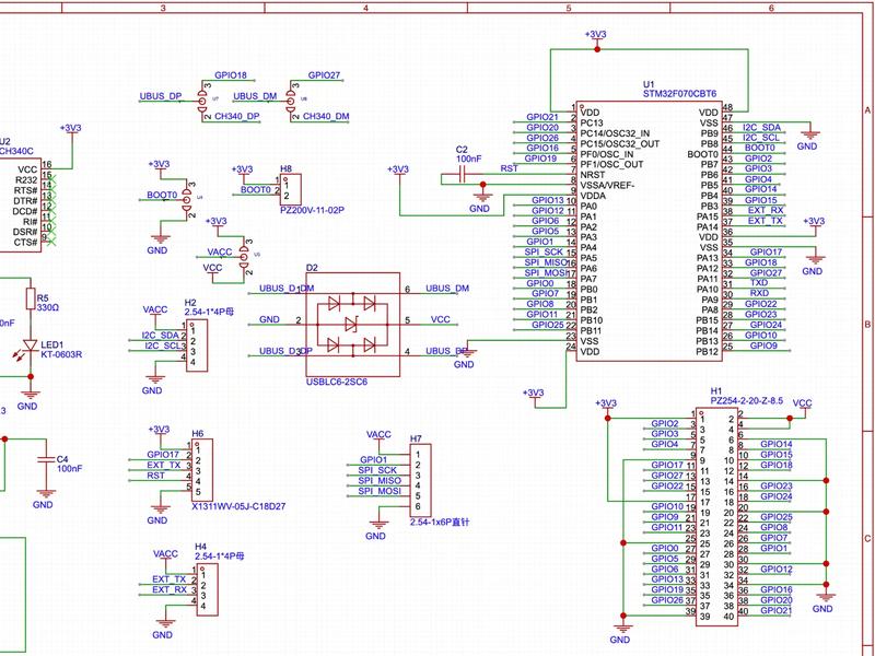
1. Schematic. The redesigned circuit: the microcontroller, the USB connection and the 40-pin header.
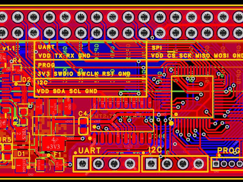
2. PCB layout. A two-layer board that keeps the Raspberry Pi-style header layout.
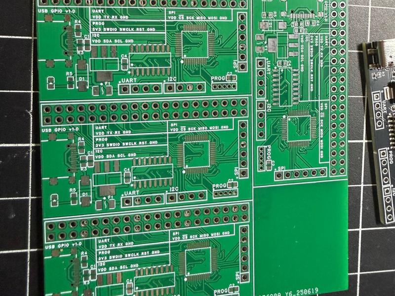
3. Bare boards. A panel of boards back from fabrication.
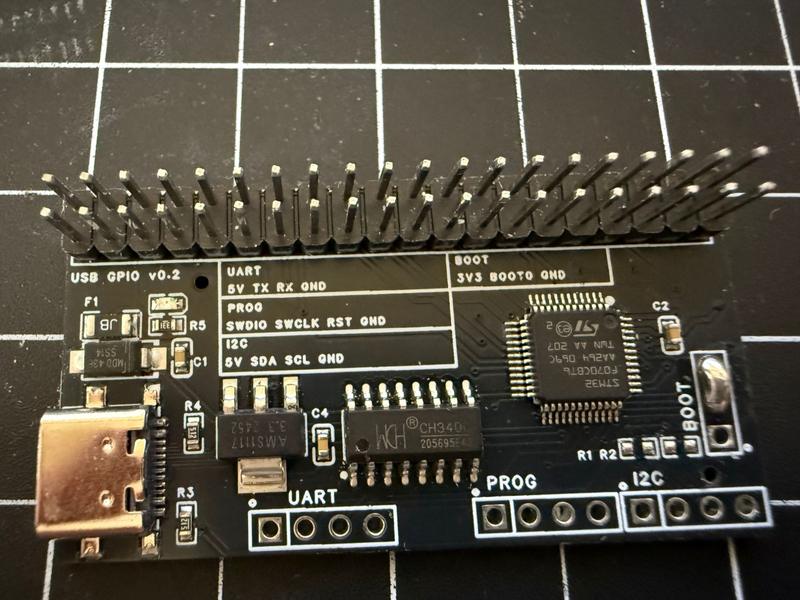
4. Assembled board. The board with its parts populated.
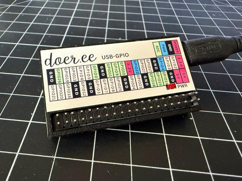
5. In its case. The finished board in its 3D-printed case, with the pinout label on top.
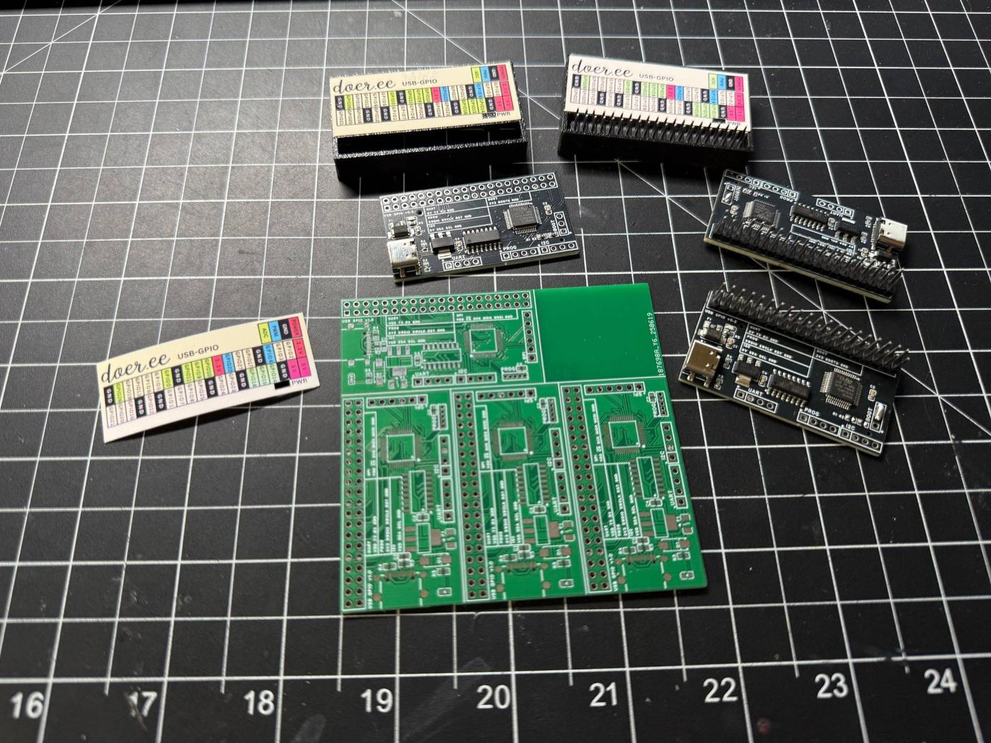
Every stage on one mat: an unpopulated panel, assembled boards, printed pinout labels and finished cases.
Resources
- Buy: Doer USB GPIO Board in the Doer shop
- Python library: DoerGPIO on PyPI · source and docs on GitHub
- Firmware: DoerGPIO_FW on GitHub · releases (read Firmware updates before flashing)
- Demo video: Digital output demonstration and introduction (also on YouTube)
- Support: hi@doer.ee
- Acknowledgment: DoerGPIO builds on the open-source RTK GPIO project by Ryanteck LTD.